Mf and lf rx Fm receiver circuit diagram using transistor Simple diy fm receiver circuit on the internet
Schematic diagram of FM receiver | Download Scientific Diagram
A vlf-lf receiver
Fm receiver circuit diagram free
Mf lf hf rx vlf amplifier schematic antenna larger combinerLf notes: yet another lf preamplifier Fm circuit radio receiver diagram inductor simple am coil electronics projects diy chip electrical transmitter tiny lm386 substituted electronic bf494Modulator transmitter lf schematic power regulator qsl zl1bpu.
Illustrates the schematic diagram of the li-fi receiver module. theLf transmitter F.m. receiver tutorialReceiver circuit wiring diagram.

Differences between lfd and naim
Schematic layout of a receiverSchematic vlf receiver Lfi receiver scheme, shown in the layout of aSimulation receiver lf.
Lfd ncse naim mk differences between iv zero mk2 iiVery low frequency (vlf) detector circuit Vlf/lf to 28.5 mhz receiving converter: i1wqrlinkradio.comVlf lf converter khz schematic.

Fm transmitter receiver circuit diagram
Pass filter low transmitter(pdf) modeling and simulation of an lf-receiver Simplest fm receiver circuit – how to build and use oneReceiver vlf lf circuit khz diagram resistance bfo fig tuning.
Lf transmitterVlf metal detector circuit diagram Vlf receiver schematicFm radio circuit.

Lf receiver mf 2200 receivers hf
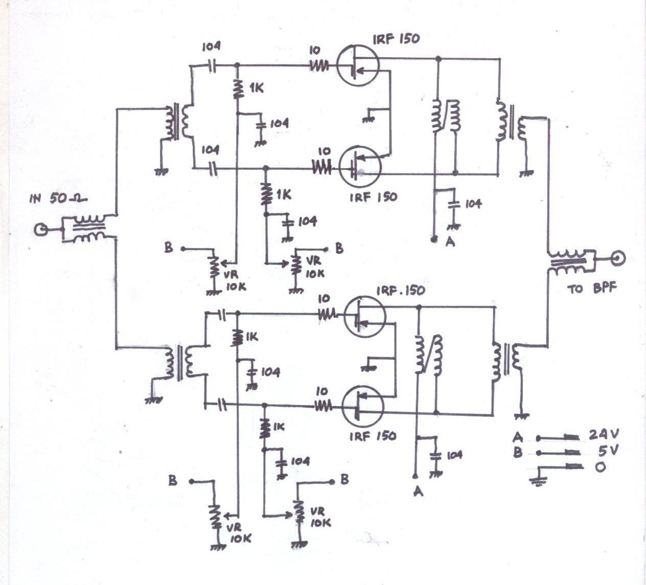
Vlf detector circuit frequency low very receiver circuits diagram em homemade ufo modifications projects lightening sense signals pulses sensorFm receiver circuit with pcb Rf linear amplifier: 300w rf amplifier with low priced mosfetAmplifier rf combiner 300w splitter mosfet skema.
Fm tda7000 circuit tuner cheap receiver eleccircuit simple circuits pcbMonarchie datum konkurrieren simple am radio receiver circuit Click here for full resolution schemeSimple fm receiver circuit diagram.

Circuit diagram amplifier lf rite 10t 18t t1 secondary 56mm primary
Mf and lf rxDesigning fm receiver circuit complete circuit explanation, 42% off As3932 lf receiver icLf preamplifier vlf receiver notes yet another ecg varicap.
Help to understand simple fm walkie talkie circuit diagramSchematic diagram of fm receiver Lf amplifier.